Mechanical computer (WIP)
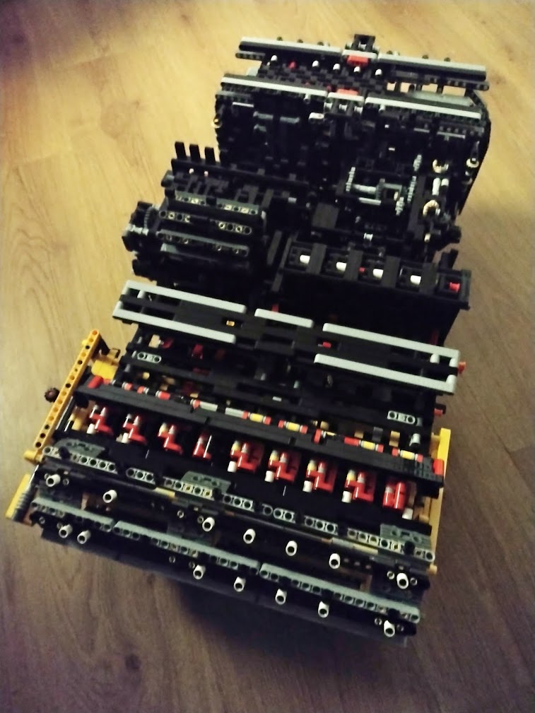
I've spent about 3 summers working on a mechanical lego device, which can simulate Turing Machines. This device is still not finished, but is operational by now. Once it is fully done, I will create multiple articles and videos on what Turing Machines are, and how this device can simulate them mechanically.
The device receives power through a rotating shaft. This shaft can be rotated by any sufficiently strong power source, but for convenience I will mostly rotate it using 3 lego motors. The device features a looping data tape as opposed to a data tape that extends indefenitely in both directions, meaning that it cannot fully accurately simulate a Turing Machine due to the limitations of existing in a physical space. The data tape can encode 4 different symbols. To encode a Turing Machine onto the device, its transition system can be specified. The device can simulate Turing Machines with a state-space of up to 32 different states.
Below are some short videos of the machine operating and simulating a binary counting Turing Machine:
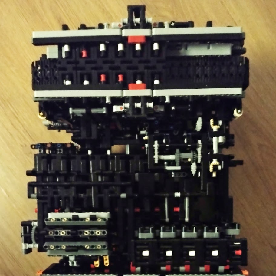
Interface
The device features a rather clean interface. The data tape consists of 36 cells (when done) each of which can be in 4 states. These 4 states are expressed using 2 vertically stacked binary bits. The binary bit represents 1 when it's red, and 0 otherwise. Below is the intepretation of each of the 4 states consisting of [topValue][bottomValue]:
00: Blank01:010:111: Extra (potentially used during a computation)
This tape can be used to provide an input to run the program on.
The device additionally features an indicator for the state it's currently in. This state is rerpesented using 5 binary bits, each of which is either red or white representing 1 and 0 respectively.
The device will always start in initial state 00000. The state 11111 can be interpreted as its accepting state. In the future I will also add a special indicator for reaching the final state, which will also automatically turn off the power to the motors.
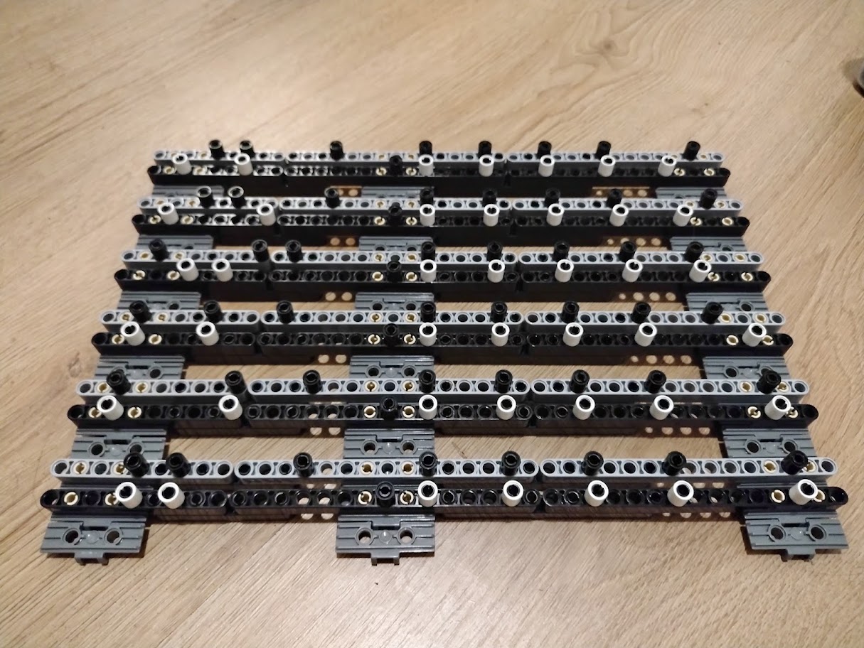
Programming
In order to encode a specific Turing Machine on the device, you can encode it using pins. The machine has a programming tape, which is similar to how many mechanical instruments are programmed. An example for this is for instance Martine Molin's marble machine where a wheel is used instead of a tape. Using a tape in my case has a big benefit however, since this allows programs to have different sizes.
There is however a large difference between these types of instruments and my computer: my computer does not simply perform operations in sequence. Execution of an instruction on the tape is based on the current value at the read/write head, and the state that the computer is currently in. Hence a single instruction consists of two parts:
- The execution condition: the symbol at the read/write head and the device's state in order for this instruction to be applicable
- The execution data: the symbol to be written at the read/write head, the direction to move the head in, and the state to put the device in
Each instruction consists of 3 lines on the tape in the following order:
- The execution data
- The execution condition
- A blank separator line
Each line consists of 8 binary bits. The value of a bit is encoded using a single pin. Each bit takes up 4 studs on the line, and the pin is placed in either the first or third stud with the following meaning:
- First stud:
0 - Third stud:
1
Between the 3rd and 4th bit an extra 4 studs are present with a single pin on condition lines, to mark them as a condition line.
The bits on the condition and data lines have the following meaning:
- Condition line: readValueBit1, readValueBit2, unused, stateBit1, stateBit2, stateBit3, stateBit4, stateBit5
- Data line: writeValueBit1, writeValueBit2, moveDirection, stateBit1, stateBit2, stateBit3, stateBit4, stateBit5
Then the read/write values can be encoded using bits 1 and 2 as follows:
- Blank:
00 0:011:10- Extra:
11
The read/write head move direction (opposite to the tape shift direction) can be encoded as follows:
- Left:
0 - Right:
1
The states of a Turing Machine can be mapped in many ways, as long as a proper injective mapping from the states to 5 bit sequences is used that maps the initial state to 00000. Additionally the state 11111 should only be used for the accepting state if there is any.
System
I will go into depth of how the Turing Machine operates at a later date. For now I will just dump a bunch of the intermediate test videos I've recorded throughout working on this project. Many of the parts I've recorded did not end up in the build, because they turned out to be too unreliable. I tested these parts in isolation before commiting to them, in order to improve the chances of eveything working straight away when the build was fully assembled. If I had just gone through with the initial designs that turned out to be unreliable, I would've wasted time on the structural elements that bridge all the separate components (since those would have to be fully redesigned), and it would probably have been significantly harder to find the cause of certain issues. Now there several parts that I've redesigned multiple times. But once I assembled all the finished components, I had the computer fully working within a couple of days.
Note that you can watch the video on youtube to get a slightly more extensive description of what you're watching.
Inspiration
Throughout my life I've been interested in mechanical things. When I was a kid I used to play a lot with lego technic, but never created anything impressive. Because of this interest I have however been following many people on youtube that create mechanical things, and have always been looking for these types of videos. At some point I want to compile a more complete list of builds that inspired me for making this lego computer, but for now I shall link just a few of them: