Sweeper
Sweeper is a tool for generating 3D meshes from a set of cross-sections and a sweep-line. It was developed for the 2IMV10 Visual Computing Project course at the TU/e. I developed it together with Boris Rokanov and Georgi Kostov.
The goal of this website is to allow people with little 3D modeling experience to easily create simple objects, while also allowing the creation of a variety of more advanced objects. The following video introduces the website, and explains how it can be used:
The application can be accessed at tarvk.github.io/3D-sweep-object
Stack
This website was primarily developed using the following libraries:
Additionally the following supporting libraries were used:
Aspects
This project had a couple of aspects that are worth discussing. The primary aspect is the actual sweep algorithm responsible for creating the meshes. But some UI and architecture aspects are also elaborated on.
Sweep algorithm
The sweep algorithm has been developed as an independent piece of code without any external dependencies. It receives the set of cross-sections together with the sweep-line and some additional settings, and outputs a 3D mesh. This mesh is defined as a set of 3D points and triples of (indices of) these points that form the triangles of the mesh.
The exact interface of the sweep function is described by the following typings:
View code
/**
* Creates a mesh from a given sweep object specification
* @param spec The specification for the sweep to perform
* @returns The created mesh
*/
function performObjectSweep(spec: ISweepObjectSpecification): IMesh;
/** The data specifying a 3d mesh */
type ISweepObjectSpecification = {
/** The sweep line to be used for the object */
sweepLine: ISweepLineSpecification;
/**
* The cross section to be swept.
* There should be at least 2 cross section specifications, for which the first should have position 0 and the last position 1.
* The cross sections should be sorted according to their position value.
*/
crossSections: ICrossSectionSpecification[];
/** The number of sample points */
sampleCount: {
/** The number of points to approximate the sweep line by */
sweepLine: number;
/** The number of points to approximate the cross sections by */
crossSection: number;
};
/** The range of the sweep line to be used */
range?: IRange;
};
type IRange = {start: number; end: number};
/** The generic part of the sweep object specification concerning the sweep line */
type ISweepLineSpecification = {
/**
* The sample function retrieves the positions to place cross sections at
* @param samples The number of samples to retrieve
* @returns The samples along this sweep line
*/
sample: (samples: number) => ISweepLineNode[];
/**
* The samplePoint function retrieves one position corresponding to the given fraction between 0 and 1
* @param per The fraction of the path to get the node for
* @returns The node at this point
*/
samplePoint: (per: number) => ISweepLineNode;
};
type ISweepLineNode = {
/** The position of the node in 3d space */
position: Vec3;
/** The direction of the cross section to place at this node */
direction: Vec3;
};
/** The generic part of the sweep object specification concerning a cross section */
type ICrossSectionSpecification = {
/**
* The sample function to retrieve the points cycle of this cross section for a given number of points
* @param points The number of points to retrieve
* @returns The approximation of this cross section with the given number of points
*/
sample: (points: number) => Vec2[];
/** The position of this cross section along the sweep (ranges from [0, 1]) */
position: number;
/** The scale that this cross section should have */
scale: number;
/** The rotation of this cross section on the whole */
angle: number;
};
/** The output mesh format */
type IMesh = {
/** The points of the mesh */
points: Vec3[];
/** The faces of the mesh, using the specified points */
faces: IFace[];
};
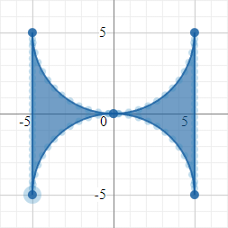
type IFace = [number, number, number];This algorithm takes a generalized sweep-line and cross-section specification, such that it doesn't have to concern itself with all the line types and controls that the UI allows for. This specification allows the algorithm to simply retrieve a number of nodes along the sweep-line, where cross-sections should be placed. It also allows the algorithm to retrieve approximations of the specified cross-sections in the form of polygons for a given number of points. This is visualized by the small points shown in the cross-section view:
The algorithm derives intermediate cross-sections to place at all the sweep-line nodes by linearly interpolating the points of the user specified cross-sections. The result of this can be seen in the following video:
The 3D shape is generated by placing the cross-sections in 3D space by translating and rotating the cross-sections. After all the cross-sections are placed, the points of every 2 consequtive cross-sections are connected into triangles of the mesh to form the walls. The first and last cross-sections are triangulated to form the first caps of this shape.
To place the 2D cross-sections in 3D space, a 3D representation of the cross-sections is created with all points having a z-axis value of 0. Homogeneous coordinates are used, such that both the rotation and translation of the entire cross-section can be expressed using a 4x4 matrix. The main challenge of this process is to ensure rotational consistency. The sweep-line only specifies what direction the normal-vector of the cross-section should point at, but this leaves the rotation of the cross-section along this normal vector unconstrained. The initial implementation of the algorithm didn't take this into consideration, which resulted in unexpected jumps in rotation. The final implementation takes the rotation matrix RM and normal direction d of the previous cross-section and given a new direction dn calculates a new rotation matrix RRM that multiplied with the previous matrix points in the new direction.
Rotate produces a rotation matrix that rotates by the given angle counterclockwise along the given axis. Using RRM we can calculate the rotation matrix for the new cross-section, and update the previous direction d:
This implementation minimizes the rotation between consequtive cross-sections along the unconstrained axis. The difference between our first implementation on the left and the final implementation on the right can be seen in the following image:

The implementation of this matrix rotation can be found in transformRotationMatrix.ts. The main entry point of the whole sweep algorithm can be found in createSweepObject.ts
UI design
One of the challenges of this project was to keep the UI clean and simple while still keeping it powerful enough to create numerous shapes. We additionally had to make sure that this simplicity does not ruin usability, since advanced features may be harder to get familiar with, but often make software easier/quicker to use in the long run.
To keep the UI simple while still allowing to get immediate feedback on changes, we decided to split the page into two sections:
- The sweep-line view (left)
- The cross-section view (right)
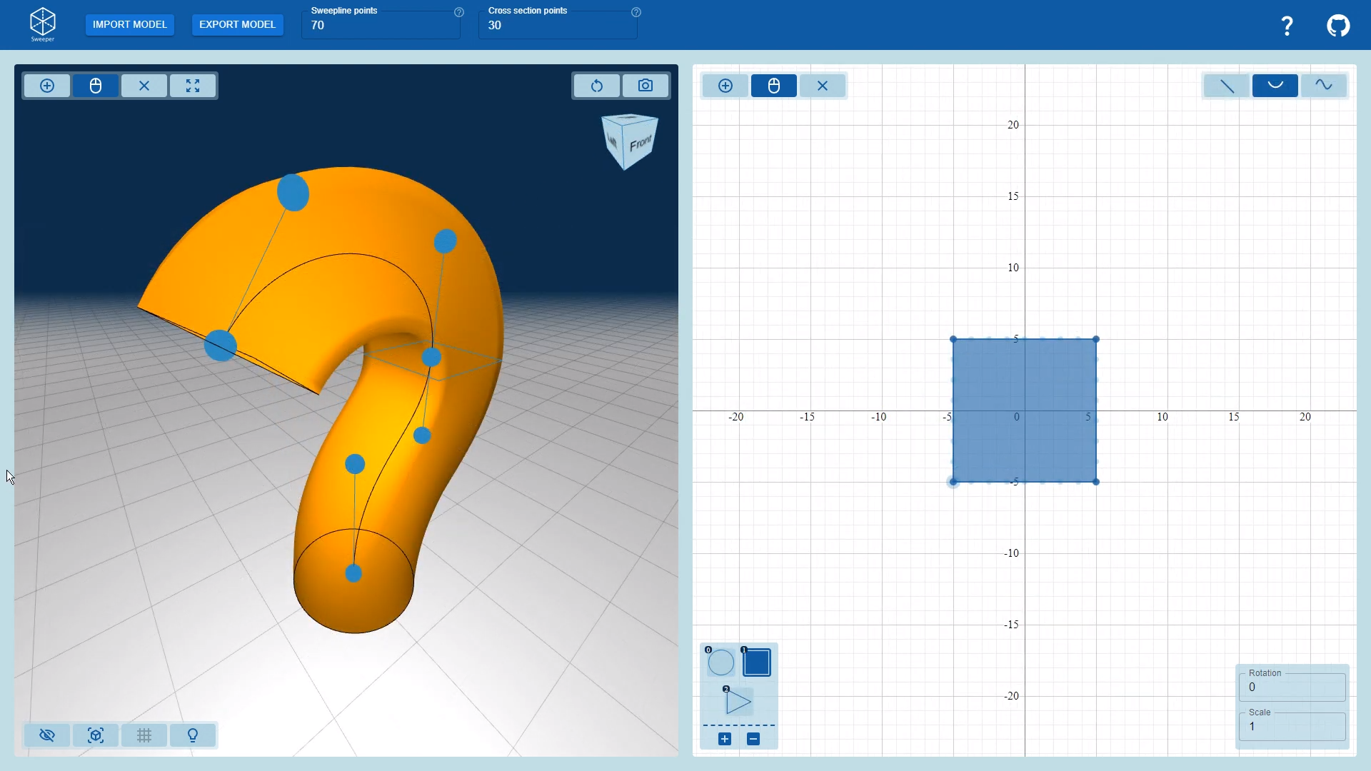
This sweep-line view doubles as the output view, allowing the users to instantly see how their changes affect the final mesh.
We also carefully thought about the camera movement in this view, since this is crytical for intuitive and convenient interactions in 3D. We placed a "view cube" in the top right, which allows for easy orientation, and even allows the user to snap into an exact direction by clicking a face. The user can also switch to an orthographic perspective which ensures that things keep the same size independent of their distance from the camera. This can help a lot when trying to aligning points.
State management
One important goal of the project was to show the user a live view of the final sweep object, such that any change is immediately reflected in the mesh. To achieve this, a data model of the sweep object specification was made. This model uses my own state management library Model-React. This allows both the sweep-line view and the cross-section view to subscribe to changes in the model such that they can instantly rerender when needed. The mesh itself is also defined in terms of the specification, such that it's instantly recalculated when changes occur.
Keeping this model separate from the views keeps this aspect of the code clean, such that we don't have messy dependencies between different components. Not using a global state model often results in messy prop passing, difficult state synchronization, and unnecessary complexity. My group members unfortunately weren't as familiar with my library as I was (which is to be expected), and some of the 3D graphics do have duplicated state as a result. In a couple of instances this indeed ended up causing bugs, due to to improper state synchronization. Defining a data model also made it easy to write code for exporting the model to a plain JSON format. There is also some code to import this JSON format to a new model, which even performs checks on the format and creates user friendly error messages if the provided data does not adhere to the format.
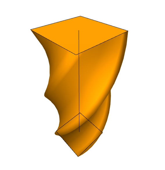
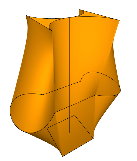
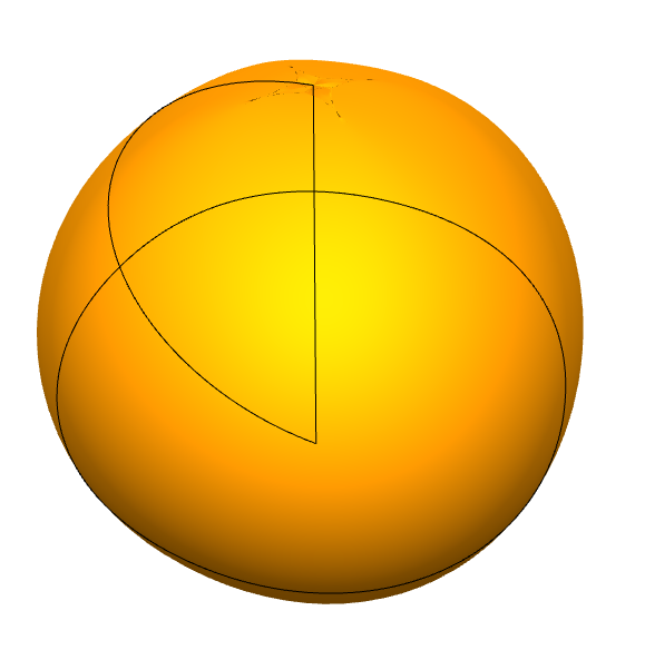
Examples
Below is a collection of images of objects generated by our application.